Interaction Between Switching Protocols: STP, vPC and HSRP
In previous blogs, we were able to give an in-depth study on these protocols. The goal of all the protocols discussed is to create a stable, scalable, efficient, and redundant Layer 2 network. The interoperability of these protocols is essential to achieving this goal.
From the study it becomes somewhat apparent that these protocols cannot exist as stand alone protocols in the data center, but have to work efficiently with other protocols
At a minimum, these protocols should coexist without impacting each other's performance. However, for optimal efficiency, they are designed to work interdependently, providing exponential benefits
This interaction is crucial for achieving optimal network performance, including faster convergence, improved efficiency, increased bandwidth utilization, and enhanced redundancy
Protocol Interactions
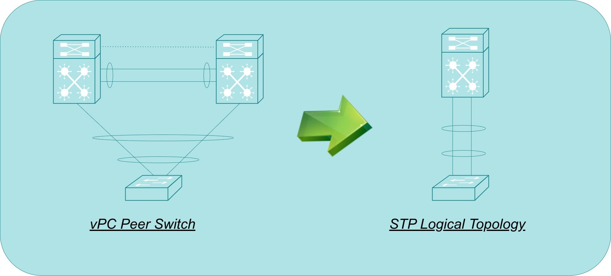
STP and vPC: vPC eliminates loops that could occur between two vPC peer devices, simplifying the STP topology. The primary vPC peer generates and processes BPDUs, while the secondary peer listens for BPDUs but does not actively generate them.
This behavior can be further optimized with the peer-switch feature, which allows the vPC pair to act as a single STP root in the Layer 2 network. Both switches share the same Bridge ID. This configuration improves convergence time because a failure in either switch causes minimal STP recalculation, as both have the same Bridge ID and either can be elected root. This also eliminates the need to pin the STP root to the primary vPC switch.
STP and HSRP: In a network where both HSRP and STP are configured, and the core switches are Layer 3 switches capable of acting as the default gateway, strategic configuration of these protocols is necessary.
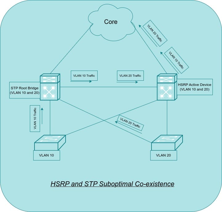
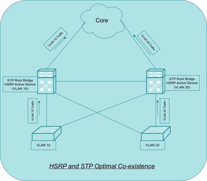
In a dual-core environment, a Root Guard configuration is typically implemented to ensure the STP root remains at the core. It would be inefficient if the STP root were on core switch 1 and the HSRP primary device were on core switch 2. This would force traffic to traverse core switch 1 before being forwarded to core switch 2 to exit the network. To optimize these protocols, the STP root and the HSRP primary device should be configured on the same device for each VLAN.
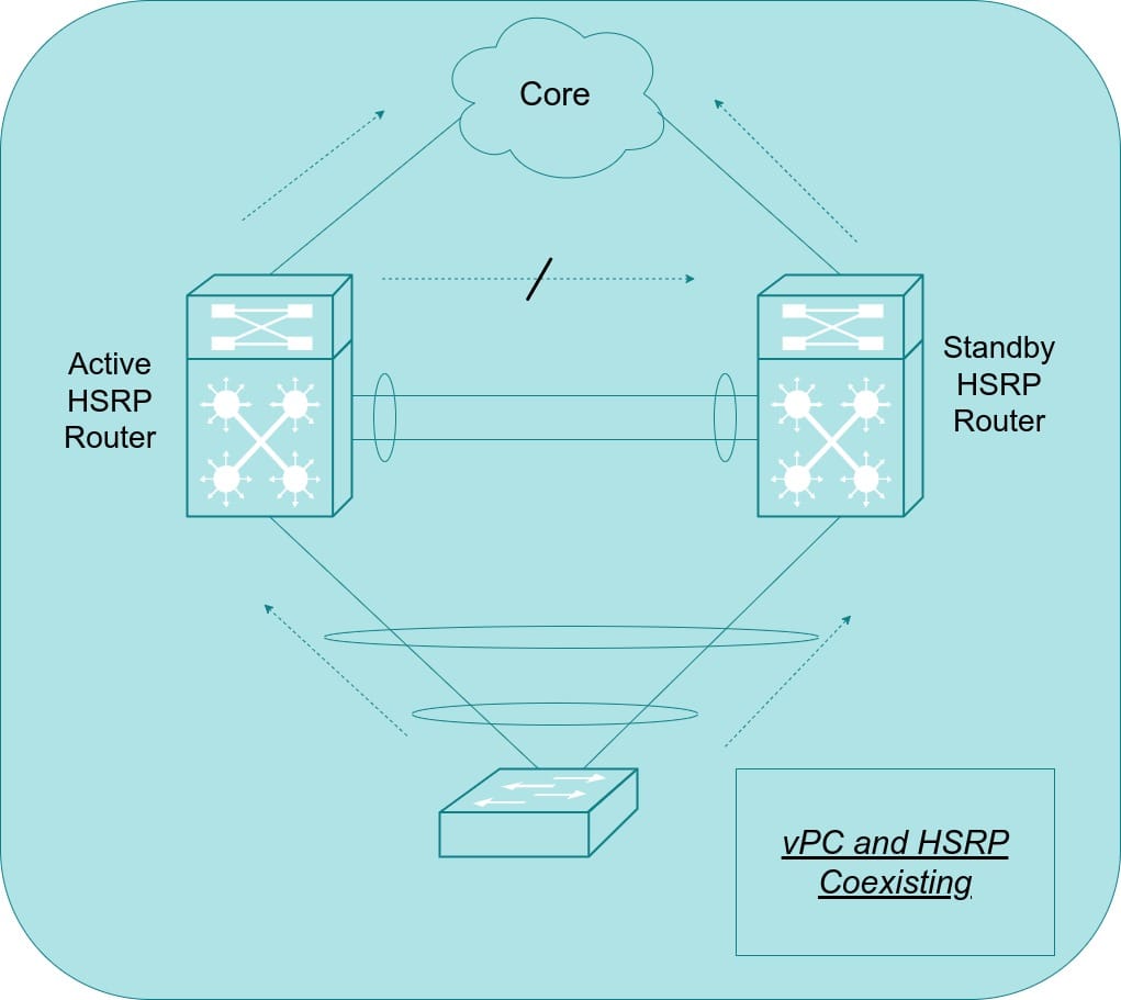
vPC and HSRP: In a vPC environment, both peer switches can forward traffic. A vPC peer only sends traffic over the peer link to the other peer if it lacks a local member port for that vPC. However, in an HSRP environment, only the active HSRP switch forwards traffic destined for the shared virtual MAC address. When vPC is configured in an HSRP environment, Cisco modifies the forwarding rules to allow standby switches to forward traffic destined for the virtual MAC address. This enhancement ensures that the vPC peer link does not carry traffic unless there is a vPC peer-link failure.
Conclusion
This concludes our study of the critical interactions between Spanning Tree Protocol (STP), Virtual Port Channels (vPC), and Hot Standby Router Protocol (HSRP) in data center environments. By understanding how these protocols work together, network engineers can build more robust, efficient, and highly available networks. Remember that careful planning and configuration are essential to maximize the benefits of these technologies.
This also marks the end of our deep dive into switching protocols in the data center. I hope this series has provided you with valuable insights into building a solid foundation for your Layer 2 network. But the journey doesn't stop here! In the next series, we'll shift our focus to routing in the data center. We'll explore essential routing protocols and techniques that ensure efficient and reliable communication between different networks within your data center. Stay tuned for an exciting exploration of Layer 3!