Preventing Network Loops with Spanning Tree Protocol (STP)
Welcome to my CCNP Data Center journey! In this blog series, I'll be exploring the key concepts of data center networking, starting with a deep dive into switching protocols. I'll assume you have a foundational understanding of networking principles as we explore these more advanced topics.
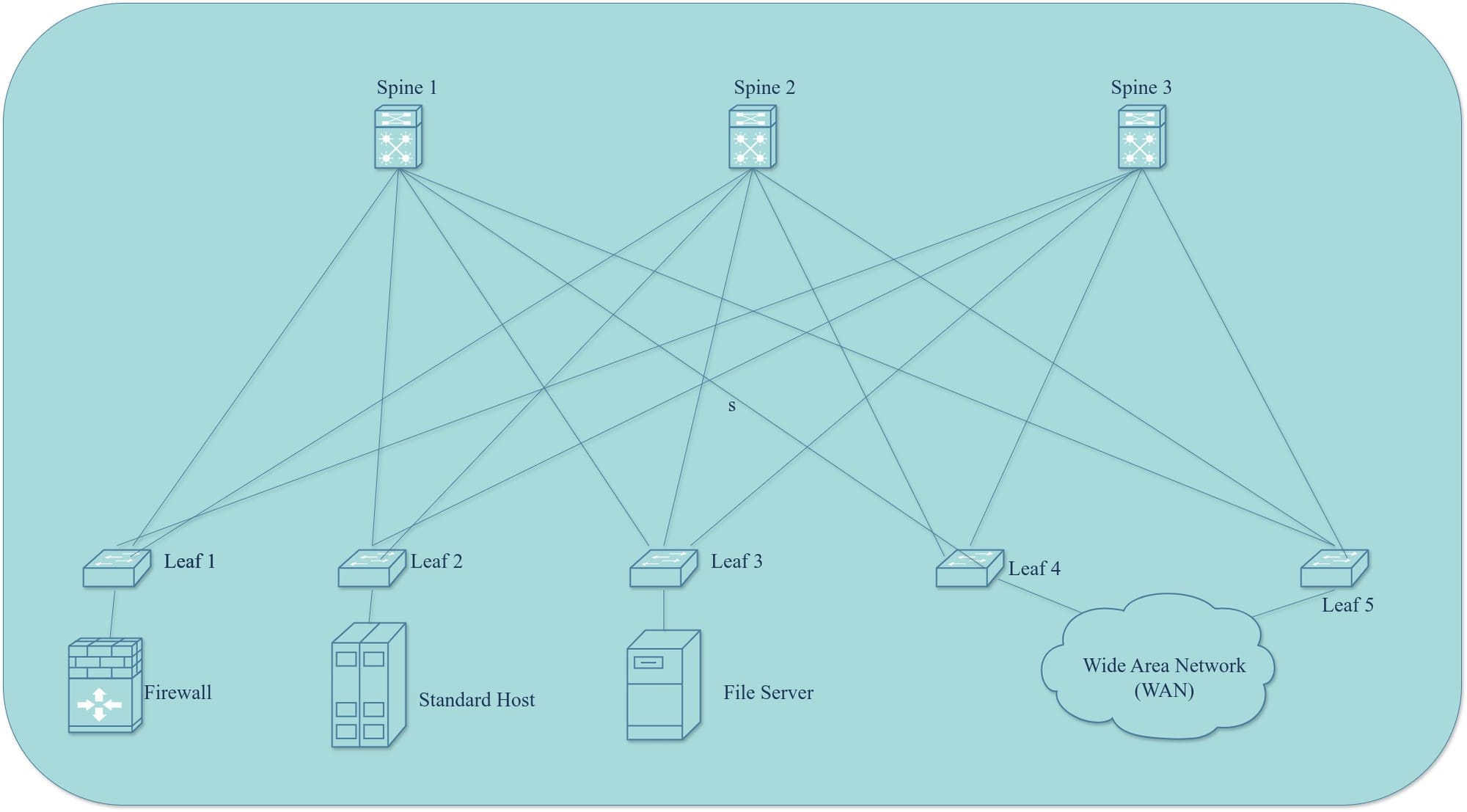
Data centers rely heavily on switching to enable fast and reliable server communication. To achieve this, servers are interconnected with each other through multiple high speed paths usually creating a mesh network. This highly redundant network could cause loops which could result in broadcast storms that have the power to take down networks
To balance the need for redundancy, load balancing, and loop prevention, Layer 2 networks utilize various protocols, including
- Spanning Tree Protocol
- Port Channels
- First Hop Redundancy Protocols
This blog post focuses on Spanning Tree Protocol
What is Spanning Tree Protocol (STP)?
In a data center network, the switching architecture often includes multiple entry and exit paths, which can lead to unending loops because Ethernet frames lack “time to live” flags. The loops could cause broadcast storms and consume all network resources. Spanning Tree Protocol (STP) prevents this by creating a loop-free logical topology. It does this by blocking redundant paths and activating them only when the primary path becomes unavailable.

What are the different versions of STP?
There are two versions of STP:
- Spanning Tree Protocol (STP) - IEEE 802.1D: The Original Standard
- Rapid Spanning Tree Protocol (RSTP) - IEEE 802.1W: An evolution of the standard that provides faster convergence times in case of network changes thereby minimizing downtime
To understand how STP achieves this loop-free topology, it's important to delve into the concepts of convergence and the root bridge election process.
What are the key concepts in STP?
- Root Bridge: This is the designated switch at the top of the Spanning Tree topology. It serves as the central point where switches forward packets to traverse the network.
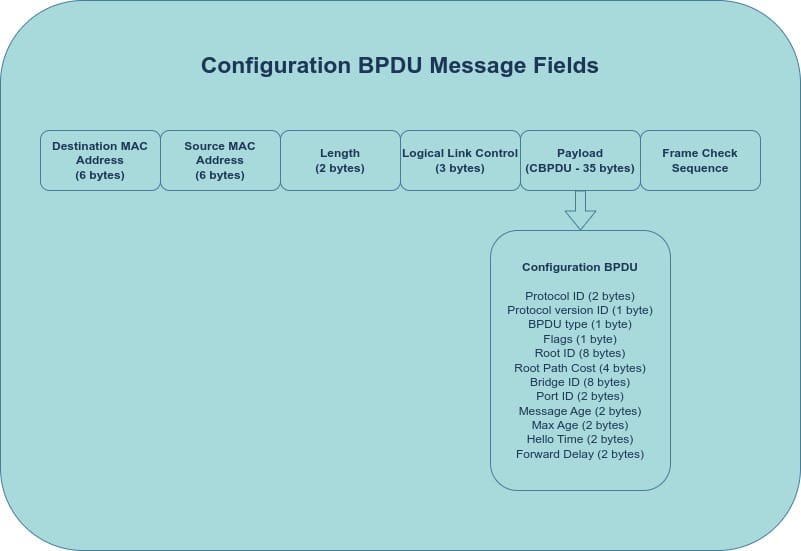
- BPDUs (Bridge Protocol Data Units): BPDUs are data units that switches use to form the STP topology. They facilitate communication and decision-making among switches. There are two main types of BPDUs:
- Configuration BPDUs
- Topology Change Notification (TCN) BPDUs
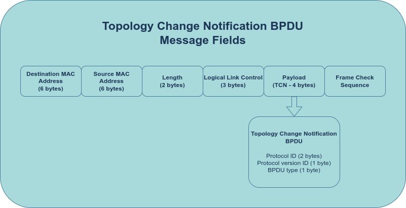
As their names suggest, Configuration BPDUs are sent by the Root Bridge to signal a configuration change like a change in the root path cost. TCN BPDUs are sent by non-root bridges to signal a network change like a port going down.
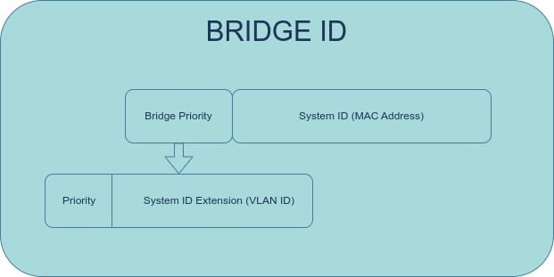
- Bridge ID (BID): A BPDU contains a Bridge ID (BID), which consists of the switch's MAC address and priority. The BID is used to elect the Root Bridge. The switch with the lowest BID becomes the Root Bridge. While all switches have a default priority of 32768, the MAC address typically serves as the tie-breaker in the root bridge election. A standard Configuration BPDU includes the Sender BID, Port ID, Root BID, and Root Path Cost.
What are the different STP port roles?
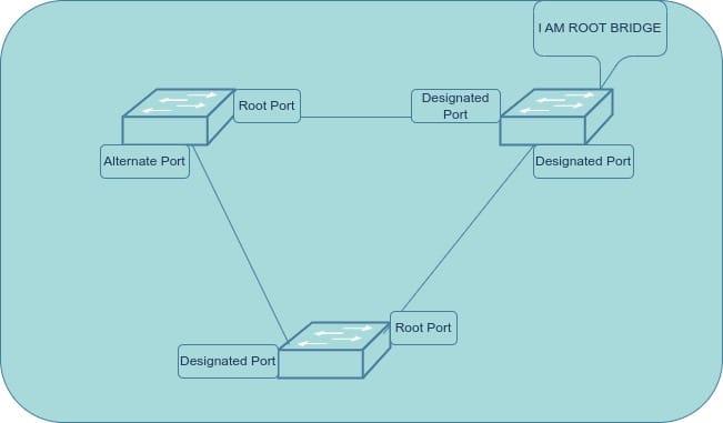
- Root Port: The port on a non-root bridge with the shortest path to the root bridge. Path cost is determined by the speed of the links; faster links have lower costs. This port forwards data towards the root bridge.
- Designated Port: The port that forwards data from the root bridge to other parts of the network. Every port on the root bridge is a designated port. Each network segment has one designated port responsible for sending traffic down that segment.
- Blocked Port: In classic STP, after the root and designated ports are selected, any remaining ports become blocked ports. These ports are blocked to prevent network loops. Blocked ports continuously listen for BPDUs. If they don't receive BPDUs for a specific interval, they assume a problem with the topology and initiate a new election process.
- Alternate Port: (RSTP only) An alternate port provides an alternate path to the root bridge. These ports are on standby and become active if the root port becomes unavailable.
- Backup Port: (RSTP only) A backup port provides redundancy for a designated port. It takes over if the designated port on a segment fails. Backup ports are rarely used in modern networks, as they are typically only relevant when hubs are present.
How does STP elect a root bridge and achieve convergence?
The STP uses the Spanning Tree Algorithm to create a loop-free network topology. It accomplishes this by continuously evaluating the optimal path through the network, starting from the top switch, which is designated as the root bridge.
Here's how the process works:
- Initial Startup: When switches are first connected to the network, they generate and send out their BPDUs.
- Root Bridge Election: The switches compare the BPDUs they receive. The switch with the lowest Bridge ID is elected as the root bridge.
- Root Port Selection: Each non-root switch identifies the port with the best path (lowest cost) to the root bridge. This port becomes the root port.
- Designated Port Selection: For each network segment downstream, the port with the best path to the root bridge is selected as the designated port.
- Blocking Redundant Paths: If multiple paths with equal cost exist, the sender's Bridge ID (and then Port ID, if necessary) is used as a tie-breaker. All remaining ports are set to the blocked state to prevent loops. (Note: This behavior is modified in RSTP.)
How does RSTP improve upon STP in terms of convergence and topology changes?
RSTP is an improvement upon STP. It builds upon the foundation of STP with several enhancements. One key difference is the addition of alternate and backup ports in RSTP.
- STP Port Behavior: After the root and designated ports are selected in STP, all remaining ports transition to the blocking state to prevent loops. If there's a change in the network configuration, the entire election process repeats, which can be time-consuming.
- RSTP Port Behavior: RSTP utilizes a caching system that allows it to assign alternate ports. These ports provide an alternate path to the root bridge and can quickly take over if the primary root port fails. RSTP also assigns backup ports, which provide redundancy for designated ports. This ability to immediately activate alternate and backup ports is one reason why RSTP converges much faster than STP.
- STP Topology Change: In STP, only the root bridge can send Configuration BPDUs to trigger changes in the network topology. If a downstream switch discovers a more efficient path, it must first notify the root bridge. This involves sending Topology Change Notification (TCN) BPDUs, which are relayed upward until they reach the root bridge. The root bridge then sends Configuration BPDUs downstream to initiate the necessary changes. This process can be relatively slow.
- RSTP Topology Change: RSTP introduces a more efficient synchronization process. Each switch can independently negotiate and implement topology changes. When a switch modifies its port roles, neighboring switches detect these changes and adjust their own ports accordingly. This distributed approach, known as the RSTP Sync Process, allows for much faster responses to network changes.
RSTP achieves faster convergence by having each switch send hello messages (keepalives) to its neighbors, enabling rapid detection of neighbor failures
If a switch doesn't receive a hello message from a neighbor within a set time, it adapts its port roles as needed. In contrast, STP relies on the root bridge to generate and propagate these timers, which can slow down the response to topology changes.
How do port states transition in STP and RSTP?
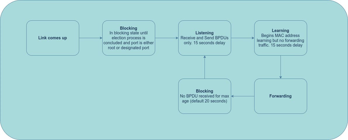
During the convergence and election process, STP ports transition through multiple states:
STP Port States
- Disabled: The port is administratively shut down.
- Blocking: The port listens for BPDUs but does not send BPDUs or forward traffic.
- Listening: The port receives and sends BPDUs but does not forward traffic. This is a transitional state that lasts about 15 seconds.
- Learning: The port receives and sends BPDUs and learns MAC addresses to build its MAC address table. It does not forward traffic yet. This is also a transitional state that lasts about 15 seconds.
- Forwarding: After the learning state, the port forwards traffic based on its MAC address table.
RSTP Port States
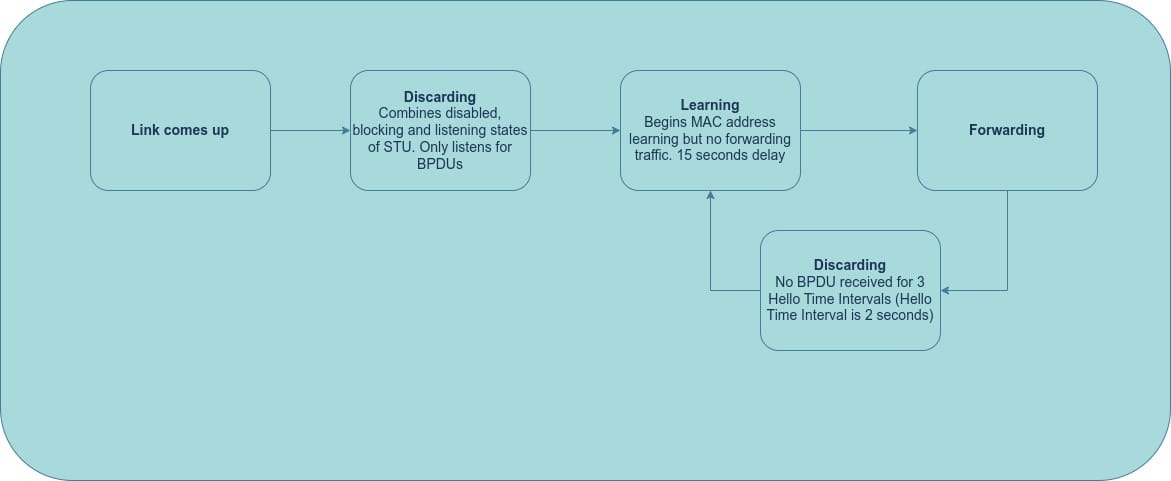
RSTP simplifies the port state transitions:
- Discarding: This state combines the disabled, blocking, and listening states of STP. The port listens for BPDUs but does not process them or forward any traffic.
- Learning: Immediately after the discarding state, the port enters the learning state, where it learns MAC addresses and adds them to its CAM table, but it still doesn't forward traffic.
- Forwarding: In this state, the port is fully operational. It receives and processes BPDUs, learns MAC addresses, and forwards traffic.
How can STP be enhanced for better performance and security?
- PortFast/Edge Ports: This feature bypasses the STP convergence delay, allowing endpoints to connect to the network more quickly. It is configured on access ports to skip the listening and learning states. Edge ports do not generate topology change BPDUs when the link state changes. However, be aware that if an edge port is connected to another switch, it could potentially cause bridging loops.
- BPDU Guard: BPDU Guard protects edge ports. If a BPDU is received on a port configured with BPDU Guard, that port is put into an error-disabled state (shut down). The port must then be manually re-enabled or automatically recovered through the error-disabled recovery mechanism.
- BPDU Filter: This feature prevents a switch from sending BPDUs on specific ports. It is often used as a workaround when connecting to an external network or a separate managed network.
- Root Guard: Root Guard prevents certain switches from becoming the root bridge. When a port configured with Root Guard receives a BPDU that would cause its switch to become the root, that port transitions to a root-inconsistent state and stops forwarding traffic. This allows you to maximize network resources by ensuring that more capable switches (like core switches) are elected as the root bridge.
- Loop Guard and Bridge Assurance: These features help detect unidirectional link failures, which can often cause confusion in the network.
- Loop Guard: If an active port stops receiving BPDUs, Loop Guard puts the port into a loop-inconsistent blocking state.
- Bridge Assurance: This feature forces ports to send BPDUs regardless of their role. It is enabled by default on RSTP. If a unidirectional link failure occurs before the link fully comes up, Loop Guard may not detect it, but Bridge Assurance will.
It's important to note that you should use either Loop Guard or Bridge Assurance, but not both.
How do PVST+ and MST improve upon traditional STP?
While STP is excellent for creating loop-free networks in the data center, blocking redundant links entirely underutilizes the available bandwidth and limits the potential of a redundant network design. To address this, Per-VLAN Spanning Tree (PVST+) was developed.
PVST+ is an enhancement to both STP and RSTP that allows each VLAN to have its own instance of STP. This means that each VLAN can have a different root bridge, enabling different VLANs to use different paths through the network. This distributes traffic across multiple links, effectively load balancing the network and increasing overall bandwidth utilization. With PVST+, the original STP and RSTP are often referred to as PVST+ and Rapid PVST+, respectively.
It's important to note that PVST+ is a Cisco proprietary feature. The industry-standard equivalent is Multiple Spanning Tree (MST - IEEE 802.1S). MST provides similar functionality to PVST+ but with the added benefit of grouping VLANs into MST instances. For example, you could configure VLANs 1, 3, and 5 to use one spanning tree instance (STP1) and VLANs 2, 4, and 6 to use another (STP2). This provides flexibility in how you manage and optimize your spanning tree topology.
Conclusion
This post explored the crucial role STP plays in building reliable, loop-free data center networks. We examined STP's core components and its evolution, including advancements like RSTP, MST, and PVST+.
This series on layer 2 switching protocols would continue with analysis on other switching protocols that ensure a robust data center network. Stay tuned!
I'd love to hear your thoughts! Leave a comment below if you have any questions or want to share your experiences with STP.